

Results 1 to 15 of 236
-
21st September, 2010, 03:06 PM #1Member


- Join Date
- May 2010
- Posts
- 50
- Thanks

- 0
- Thanks

- 5
- Thanked in
- 2 Posts
 BMW K+CAN INPA/SSS/DIS/CARSOFT/NAVCODER usb interface idiot proof
Hi guys, first of all, this isn't new but all info is spread over there and it's a bit difficult to get all info together so i made this post
1# buy some Vagcom cable KKL 409.1, just 8 ***8364; + shipping from ebay, ask the seller if it has the chip FT232RL. why? well basically because that chip support software mods.
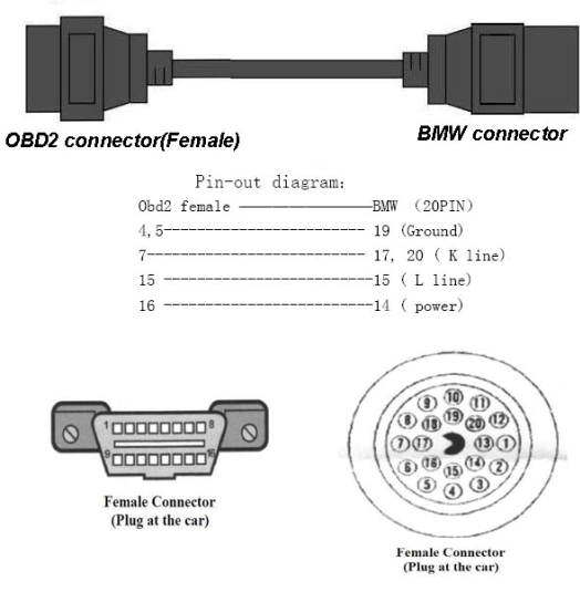
2# As my 530d do not have odb2 connector, I order a cable adapter from obd2 to 20 pin bmw, ebay seller is ( Car.Doctor ) another 8 ***8364; + shipping.
I preferred to catch it on ebay, because it was more comfortable and cheaper than going to catch the pieces out there, also for those wishing to DIY, I leave the chart with specific connections.
3# Open your vagcom and solder obd2 pins 7 and 8, which are the K lines, otherwise you will not be able to access to all modules from the car

4# If you have buyed vagcom with ftdi 232 rl, for the software mod, you will need this driver "CDM 4.2.1916 WHQL certified" , so unpack it, connect the cable, and install all with this driver.
Now we need to adjust the serial port, press the Windows key and Pause (both), then follow these images (sorry my XP is in spanish language)
Select com1 and 1 or 2 ms of latency

5# Download the "M. Prog 3.5" to modify the programming of the eeprom FT232RL,
we need to invert RI # and DSR # signals to fool the detection of battery and ignition, in order to be able to encode.
Run mprog and follow this steps
check your I / O Controls settings, them must be like this:
#C0 = RXLED
#C1 = TXLED
#C2 = PWRON
#C3 = PWRON
#C4 = SLEEP
and do this

now you should see black dots

Last edited by yorugualoco; 15th December, 2010 at 02:31 AM.
-
The Following 2 Users Say Thank You to yorugualoco For This Useful Post:
-
21st September, 2010, 03:07 PM #2Member
- Join Date
- May 2010
- Posts
- 50
- Thanks
- 0
- Thanks
- 5
- Thanked in
- 2 Posts
if your vagcom comes with ft232bm/bl chips, don't worry you only need to do some work
for those chips
pin 17 is GND
pin 18 is RI
pin 20 is DSR
so you need to solder pins 17,18 and 20 of the FTDI chip (this applies to the BL and BM) like this

but if we want some REAL battery and ingnition detect, we must do this circuit
Note: if you don't do this circuit you will not be able to do CAR KEY MEMORY
1 resistance of 4.7 kohm
1 resistance of 10 kohm
1 transistor BC546

in ft232bm/bl, it look like this


In case anyone wants to do it in the FT232RL here are the outputs of the chip.

Note: This interface supports cars from 96/98 to March 2007
it work's with inpa,dis,sss, carsoft 6.1.4 and navcoder also
For the navcoder you usually need a RESLER interface but you don't really need it
The Resler interface works with 4 outputs (ibus, 12v, gnd and NTSC) NTSC signal is used to the camera and as we don't have the chip for its management, just forget about it.
With this in mind, connect three cables as follows

OBD2 connector pin 16 to 12v Positive cable
OBD2 connector pin 7 to I-Bus cable
OBD2 connector pin 4 or 5 to negative (gnd) cable
Anyway just plug it into your obd2 and start navcoder or connect it to your cd changer or radio, whatever.
you could search in wds for your car wires you will need 12v, gnd, and i-bus wich is usually a white and yellow cable
now you can use navcoder or other i-bus softwareLast edited by yorugualoco; 21st September, 2010 at 03:20 PM.
-
The Following 3 Users Say Thank You to yorugualoco For This Useful Post:
Col19 (26th October, 2019), kronk92 (1st January, 2017), wacki_dani (1st January, 2014)
-
21st September, 2010, 06:18 PM #3DK Veteran

- Join Date
- Jun 2009
- Location
- In The Workshop Or At The Pc
- Posts
- 772
- Thanks
- 21
- Thanks
- 33
- Thanked in
- 27 Posts
Nice job mate,
Very usefull, and well explained. Still in the workshop.
if this post was use full
please press
the thanks button

-
The Following User Says Thank You to the_riddler For This Useful Post:
ptserwis2 (2nd March, 2020)
-
21st September, 2010, 09:43 PM #4Member

- Join Date
- Dec 2008
- Location
- Cyprus
- Posts
- 43
- Thanks
- 0
- Thanks
- 2
- Thanked in
- 2 Posts
Excelent job m8!!!
I will try it.
Very interesting solution!!!
-
22nd September, 2010, 08:48 PM #5Newbie

- Join Date
- Sep 2008
- Location
- Romania
- Posts
- 10
- Thanks
- 0
- Thanks
- 12
- Thanked in
- 2 Posts
hello!
nice job..great post
i have some question for you.
tell me please...the reverse signal #RI and #DSR is availble only for FT232RL , or to be made and the FT232BM/BL ?
thank`s in advance
-
22nd September, 2010, 09:03 PM #6Member
- Join Date
- May 2010
- Posts
- 50
- Thanks
- 0
- Thanks
- 5
- Thanked in
- 2 Posts
FTDI232BM/BL DON'T SUPPORT SOFTWARE MOD, so you need to do it hardware, that's why you must solder chip pins 17,18 and 20. Originally Posted by azazell

-
23rd September, 2010, 06:49 AM #7Newbie
- Join Date
- Sep 2008
- Location
- Romania
- Posts
- 10
- Thanks
- 0
- Thanks
- 12
- Thanked in
- 2 Posts
thank you
after i write the message i find the answer
yes,i soldering the pins 17,18,20 with rezistance and transistor an it`s working.
the test machine it was a BMW 320TD 2004 and the software i use is ""BMW INPA 5.02 & EDIABAS 6.47 "" (63 Mb) - i confirm its working fine
thank`s for usefull post
-
The Following User Says Thank You to azazell For This Useful Post:
Col19 (26th October, 2019)
-
7th October, 2010, 12:48 PM #8Newbie
- Join Date
- Apr 2010
- Posts
- 1
- Thanks
- 0
- Thanks
- 0
- Thanked in
- 0 Posts
Thanks for this excellent info!
Do the USB-interfaces have the same chips? If not, is it possible to modifiy the USB-IFs to?
-
11th October, 2010, 03:31 PM #9DK Veteran

- Join Date
- Sep 2010
- Location
- in the midst of war
- Posts
- 392
- Thanks
- 0
- Thanks
- 85
- Thanked in
- 16 Posts
Hello friends, where can I find the BMW INPA 5:02 & 6:47 EDIABAS "(63 Mb), I have changed the cable, now wanted the software that you tested.
To test this solution....
regards
fifas):
-
13th October, 2010, 10:03 AM #10DK Veteran


- Join Date
- Sep 2009
- Posts
- 330
- Thanks
- 5
- Thanks
- 169
- Thanked in
- 49 Posts
great post yorugualoco!
something similar for carsoft MB? (vag kkl interface modding)
i didnt manage to make it work on c220 2004 with bare factory unmodded interface and 7.6 kkl ipejasinovic version
thanks m8
un post genial yorugualoco!
algo parecido para MB? (modificando la interfaz vag kkl)
no logr? hacerla funcionar tal como viene en un c220 2004 con la version 7.6 kkl de ipejasinovic
gracias colega
-
16th October, 2010, 03:22 PM #11DK Veteran
- Join Date
- Sep 2009
- Posts
- 330
- Thanks
- 5
- Thanks
- 169
- Thanked in
- 49 Posts
one more question: Originally Posted by yorugualoco
in case of FT232BM/BL based interface, do i still need to solder obd2 pins 7 and 8?
thanks
edit: soldering pin 7 and 8 of interface is only necessary in case you connect interface directly to car by means of its obd2 16pin connector (pin 7 and 8 are k lines of 16pin obd2 connector in your car).
if your car has round 20pin connector and you use 16pin to 20pin adapter, it is not necessary to solder because pins 17 and 20 (k lines of round connector in your car) are internally soldered to pin 7 of interface (k line of interface)Last edited by manocao; 26th October, 2010 at 11:15 PM.
-
16th October, 2010, 11:43 PM #12Newbie
- Join Date
- Oct 2010
- Posts
- 7
- Thanks
- 0
- Thanks
- 0
- Thanked in
- 0 Posts
thank very good infomation is work 100%
-
17th October, 2010, 02:03 AM #13Member
- Join Date
- May 2010
- Posts
- 50
- Thanks
- 0
- Thanks
- 5
- Thanked in
- 2 Posts
yes sure, you MUST do it, otherwise you won't be able to access all modules from the car Originally Posted by manocao
Siempre hay que soldar los pins 7 y 8 del obd2, corresponden a las dos lineas K de bmw, si no los sueldas no puedes acceder a todas las centralitas del coche (solo podras acceder al motor y la caja de cambios)
-
25th October, 2010, 09:36 PM #14Newbie
- Join Date
- May 2010
- Posts
- 4
- Thanks
- 1
- Thanks
- 3
- Thanked in
- 2 Posts
Perfectly described and works... thanks!!!!
-
26th October, 2010, 10:19 PM #15DK Veteran
- Join Date
- Sep 2009
- Posts
- 330
- Thanks
- 5
- Thanks
- 169
- Thanked in
- 49 Posts
hi yorugualoco,
some questions,
i have modded my vag com kkl interface with ft232BL (not RL) as you said and installed inpa (loader 4.4.7, bmw group rectification programs uk v3.01) but when i connect interface to computer and start inpa (_.ipo) i only get battery on = black dot (ignition is off = white dot)
i have conected interface to 220v/12v ac/dc power adapter (+12v to pin 16 and gnd to pin4+5) but i get the same results
will ignition dot turn black when connecting interface to car so that pin1 is also powered? or what is the problem?
thanks
edit: exactly! it works! i have powered pin 1 of interface and i get both black dots!
in your picture both dots are black without connecting interface to car ?????
edit: sure, because your interface got no transistor, so it doesnt depends on pin1 to make ignition dot black
for car key memory we must do next circuit but it says pin 1 is ignition (instead of +12v by pin16) so i understand that in bmw cars pin 1 gets powered when turning the key to ignition position
edit: according to pinouts.ru, pin 1 is +12v (power) so i asume it only got power when key is turned to ignition position, BMW OBD-II diagnostic interface pinout and wiring @ pinoutsguide.com
i suppose that in car key memory process, inpa must detect in certain moment that key is turned to off position but with interface still plugged to car, showing battery black dot and ignition white dot.
if so, what about cars with round 20 pin connectors? in 16pin-to-20pin adapters, pin1 of obd2 side is not connected to any pin of round side so that it will never be powered, so car key memory is not supported?
edit: according to pinouts.ru, pin 16 in round bmw connector is +12v ignition but it is not taken into account in obd2-to-bwm adapter, so i suppose that for car key memory we should also solder a copper wire from pin 16 of bmw side to pin 1 of obd2 side
BMW OBD II vehicle diagnostic connector pinout and wiring @ pinoutsguide.com
in adapters from ebay, it seems round side can be opened but not obd2 side, so it is not possible to solder a wire between them.

i think for cars with 20pin connectors only solution is:
- we dont need transistor circuit anymore, just add a switch between pin 20 of ft232bm/bl and ground (pin 4 or 5 of obd2 connector in interface, or pin 17 in ft232bm/bl chip, or black wire of usb connector in interface, etc... but pin 17 and 18 must still be soldered together): switch it off when you are prompted to turn key to off position, in other conditions keep it on
- in case you wanna keep your transistor circuit (for obd2 16pin connector compatibility, in case you need it in the future or interface is also gonna be used in other bmw cars with 16pin obd2 connector), solder the 10k resistor to both pin16 and pin1 of obd2 connector in interface, BUT you MUST insert a switch between the resistor and pin16 in order to simulate key is turned to off position when prompted: switch it off when you are prompted to turn key to off position, in other conditions keep it on (except when used in bmw car with 16pin obd2 connector: keep it always switched off because pin1 will be the one powered or not when turning the key to ignition position or off position respectively)
SAY THANKS!!Last edited by manocao; 27th October, 2010 at 09:44 AM.

 Reply With Quote
Bookmarks