

 Reply With Quote
Hi!
What is the difference between the regulators?
0281002150
0281002432
0281002431
0281002173
?

Results 1,306 to 1,320 of 1429
-
2nd August, 2019, 06:53 AM #1306Member


- Join Date
- Oct 2016
- Location
- Serbia
- Posts
- 47
- Thanks

- 21
- Thanks

- 4
- Thanked in
- 3 Posts
 The timing valve is blown, is it all the same as I connect the wires of another timing valve to the PCB?
 Originally Posted by TR0UBLESH00TER

Послато са SM-N950F помоћу Тапатока
-
12th August, 2019, 06:55 PM #1307Newbie
- Join Date
- Dec 2013
- Posts
- 10
- Thanks
- 2
- Thanks
- 2
- Thanked in
- 2 Posts
-
20th August, 2019, 09:51 PM #1308Top Poster
- Join Date
- Mar 2013
- Posts
- 144
- Thanks
- 68
- Thanks
- 66
- Thanked in
- 29 Posts
If you wonder why errors show up when you put key on is because pump make a small 3 amp test when key is on
L.E. Tryed 3 times to upload a picture , not workingLast edited by TR0UBLESH00TER; 20th August, 2019 at 09:54 PM.
-
23rd August, 2019, 12:09 PM #1309Newbie
- Join Date
- Oct 2009
- Posts
- 7
- Thanks
- 1
- Thanks
- 0
- Thanked in
- 0 Posts
Hi guys!
There is any solutions for repair PSG16 pump?
Thanks in advance.
-
23rd August, 2019, 12:30 PM #1310DK Veteran


- Join Date
- Dec 2010
- Location
- Ireland ;)
- Posts
- 3,628
- Thanks
- 1,038
- Thanks
- 2,830
- Thanked in
- 1,793 Posts

PRESS THANKS AND REPUTATIONS (STAR) BUTTON
I don't give others the password to the file. I'll send my file and I'll try to make it
-
30th September, 2019, 06:52 PM #1311Newbie
- Join Date
- Sep 2019
- Posts
- 4
- Thanks
- 3
- Thanks
- 0
- Thanked in
- 0 Posts
Hey guys,
I have a Ford Transit 101PS Diesel.
The Car was at the German Bosch Service. The diagnostics told me the following fault codes:
Fault code 5C:
Fault description:
- CAN bus fault (sporadic)
Possible cause of fault:
- Fault in signal between tester
and pump control unit
- Pump control unit defective
- Wiring connection defective
- Fault in communication between
engine control unit and pump
control unit
Fault code 52:
Angle sensor/IWZ system
Is it possible that a defect voltage regulator causes the fault?
To my mind I have to remove the fuel pump and check if the voltage regulator produces 5V.
Maybe you can give me some advice?
Can also a defect Transistor cause the fault?
Best Regards
Simon
-
3rd October, 2019, 12:37 PM #1312Member
- Join Date
- Jul 2010
- Posts
- 47
- Thanks
- 7
- Thanks
- 6
- Thanked in
- 3 Posts
Hi, Originally Posted by unimetal
I have investigated VP44 quite a lot.
When no communication with VP44 is shown, it is very likely to be 5V regulator. When it comes under approximately 4.8V, electronics stops responding.
This kind of problem mostly appears on "younger" electronics, that has been replaced during official Bosch service refurb. Haven't seen many of initial built failed that way.
About transistors mentioned in this thread. I tested all of them and many more.
The red wire you'll find in first photo is conected to back-up gate position of transistor when original pad is burned. Do not heat that small gate pad on the transistor over 340 degC. Short time only.
IRF 540 has way too big input impedance.
IRF44N, 48N generally work on all applications. Quite a few I had built in had bad acceleration respond. I replaced with same transistor and it problem was cured (not always, sometimes I used 2905 instead).
I have ordered Infineon 2905 over Farnell each time. I got items that were 100% good, after 2 months I reordered same items and 2 of 2 failed while on test bench. I discharged rest of supply. Same story with other types of IC's.
For the record.
I got in an Opel pump I repaired 5 years ago, since car was scrapped due to a rust. I took off 2905 and put it on Ford Mondeo xxxxx021 pump. It failed within a month, taking down solenoid too.
Like mentioned before in this thread, this is not a 100% sure repair.
What I would like to expose is, when anybody of you guys knows the way to solder RPM capacitor back to the plate.
I've seen it couple of times, but never managed to perform it myself. Photos of what I am talking about are attached. This type of failure is not so common, but some 10% of pumps have it. When ECU shows pump RPM failure, it is this think, not RPM sender usually.
So tip, how to do it are quite welcome from you experts. (Solder wire type, soldering temperature...)
Thanks
-
The Following 4 Users Say Thank You to vagdoctor For This Useful Post:
SERBAN 70 (25th June, 2023), TR0UBLESH00TER (3rd October, 2019), unimetal (3rd October, 2019), UnQ (9th December, 2021)
-
3rd October, 2019, 05:48 PM #1313Top Poster
- Join Date
- Mar 2013
- Posts
- 144
- Thanks
- 68
- Thanks
- 66
- Thanked in
- 29 Posts
When no communication with VP44 is shown, it is very likely to be 5V regulator>>>>Agree 100 %
I got in an Opel pump I repaired 5 years ago, since car was scrapped due to a rust. I took off 2905 and put it on Ford Mondeo xxxxx021 pump. It failed within a month, taking down solenoid too.>>>>> Did you noticed that that Ford has different type of valve than Opel ?Also Ford valve eat almost 20 amps when Opel ones just 8 amps ,from my experience most of returns are from Ford vehicles ,none from Opel or others, maybe 20 amps peak require more cooling ?
What I would like to expose is, when anybody of you guys knows the way to solder RPM capacitor back to the plate.
I've seen it couple of times, but never managed to perform it myself. >>>>If something it is too hard to do ,make it easier !In this case I would replace SMD capacitor with a classic THT type capacitor ,much more easier to solder .
I saw once a repaired module where those 2 SMD caps were 90 degrees twisted ,exposing soldering pads .
Recently I begun to look more careful at the real cause of pump failure and noticed there are 3 types of transistor failure :unsoldering ,shorting and leg breaking .But not always (especially if you found transistor just unsoldered ) replacing transistor solve the pump.Had one which not perform as expected ,had to re do the job (rpm sensor changed )
-
3rd October, 2019, 08:42 PM #1314Newbie
- Join Date
- Sep 2019
- Posts
- 4
- Thanks
- 3
- Thanks
- 0
- Thanked in
- 0 Posts
Thank you for your reply! Originally Posted by vagdoctor
Today I made some resistance measurements. Everything seems to be ok.
Tomorrow I will test if there is 5V at the RPM Sensor as shown in the picture (stolen from somebody in this thread, just added the pinout info).
Maybe someone can help me to complete the image?
Does anybody know the complete pinout? The third pin from the top should be the Signal. But which signal do you expect at the fourth pin from the top?
If you want, I can make some Screenshots. I will make the measurement with the DSO. But it would be nice, if I know, what I can expect there
Best regards
Simon
VP44_Messung_Drehwinkelsensor_1.JPGLast edited by unimetal; 3rd October, 2019 at 08:44 PM.
-
4th October, 2019, 09:51 AM #1315Member
- Join Date
- Jul 2010
- Posts
- 47
- Thanks
- 7
- Thanks
- 6
- Thanked in
- 3 Posts
I checked again. Quantity adjuster solenoids are the same on Ford's and Opel/Wauhhall VP44 pumps, juddering by its MPN. Current might be different. And of course, cooling is the most important for long life. Originally Posted by TR0UBLESH00TER
About capacitor, I am not sure if I pointed it right.
Due to a constant pump hammering RPM sender capacitor sometimes looses its contact to PCB. One side of it leads to 4-th pin of RPM sender, while for the other side I haven't found a back-up soldering place. So the best way is to solder it back on place. It can be done , as seen on my photos before. It is not my work, although I wish I could say it is I really tried to learn this "know how", giving a try on some 5 "study" electronics, but unsuccessful, evidence attached . Solder just doesn't want to stick firmly.
So the real question is. Does anybody of you experts know the procedure how to perform it and of course want to share?
Respect.
IMG_20191004_094915.jpg
-
4th October, 2019, 10:59 AM #1316Top Poster
- Join Date
- Mar 2013
- Posts
- 144
- Thanks
- 68
- Thanks
- 66
- Thanked in
- 29 Posts
Some say that rpm sensor is Hall type ,which I don t agree ,others says that it contain also an temperature sensor and others says that is an double inductive type sensor ,which output 2 sine waves with different phase . Originally Posted by unimetal
I usually rely only on resistance check vs pin 1:1-2 about 90 ohms,1-3 and 1-4 a little higher ,about 100 ohms .
-
The Following User Says Thank You to TR0UBLESH00TER For This Useful Post:
unimetal (5th October, 2019)
-
5th October, 2019, 11:18 AM #1317Newbie
- Join Date
- Sep 2019
- Posts
- 4
- Thanks
- 3
- Thanks
- 0
- Thanked in
- 0 Posts
@TROUBLESHOOTER
Thank you for your reply. Yesterday I made some measurements. I opened the cover of the PSG5 and soldered some wires to the RPM sensor.
I agree to your assumption that its not a hall type sensor. I made the measurements with coupling capacitor (AC measurement).
To my mind there is no temperature sensor integrated
My RPM Sensor seems to be ok. I guessed that this Signal is symmetric to eliminate electrical noise.
But the measurements told me another information. I guess that the phase difference is caused by the different position of the sensor.
3# let me suspect that the addition of the signals could be necessary to detect the TDC/Injection Timing?
Maybe you have any ideas?
1#
Channel 1 between 2 (Sensor GND) and 3.
Channel 2 between 2 (Sensor GND) and 4.

2#
Channel 1 between 2 (Sensor GND) and 3.
Channel 2 between 2 (Sensor GND) and 4.
Channel 3 = Channel A - Channel B
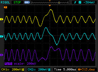
3#
Channel 1 between 2 (Sensor GND) and 3.
Channel 2 between 2 (Sensor GND) and 4.
Channel 3 = Channel A + Channel B

My next step is to remove the pump and follow the signal. I suspect that the signal is lost on the way to the coupling capacitor. What do you think?
I am excited which way it will continue.
Best Regards Simon (:Last edited by unimetal; 5th October, 2019 at 12:46 PM.
-
5th October, 2019, 07:40 PM #1318Top Poster
- Join Date
- Mar 2013
- Posts
- 144
- Thanks
- 68
- Thanks
- 66
- Thanked in
- 29 Posts
Don t get too excited ...because of hybrid technology used in control module ,there are only few faults that can be repaired ,I see only 5 :
-transistor (diagnose in pump connector never give an error code when transistor fail ,which make think diagnose is crap ) ,no pulses for quantity solenoid
-5 volts regulator ,no diagnosis via pump connector ,current consumption is zero instead of 150 mA
-rpm sensor itself
-soldering of smd cap
-quantity solenoid with shorted turns ,visible on scope with current clamp ,which cause transistor failure .
These 5 are only electrical faults ,but are also a lot of mechanical faults ,parts stucked or with wear ,these require a lot of time to disassemble,check and assemble .As time pass ,value of cars decrease and job labor also ,the end of these type of repairs is soon...
-
6th October, 2019, 04:52 PM #1319Member
- Join Date
- Jul 2010
- Posts
- 47
- Thanks
- 7
- Thanks
- 6
- Thanked in
- 3 Posts
End is soon, that's correct
-
8th November, 2019, 06:11 PM #1320Top Poster
- Join Date
- Mar 2013
- Posts
- 144
- Thanks
- 68
- Thanks
- 66
- Thanked in
- 29 Posts
In order to prevent damage of gate pad it is advisable to not direct heat it with soldering iron tip .Just put the wire near the pad ,heat it with iron ,apply solder to wire and let it drop to pad .
If transistor fail again ,dont unsolder gate wire from the pad ,just leave it there and reuse it.
Found some videos on YT about VP44 ,most of them in russian .I ve noticed they use to unscrew a T30 port near the exit pipes to measure internal pump pressure (from 8 bars at idle to 30 at 4000 rpm ) ,which would be a good indicator of mechanical state of the pump.
https://www.youtube.com/watch?v=r3bu...v8FxF&index=29
Does anyone know a test which can show mechanical condition of the pump ,before trying to repair electronic module ?I have too many failed attempts ,car don t start or car broke again soon ....Or which are the symptoms
for mechanical problems that will cause fail of electronics?Until now it seems that most successful are when the car stop suddenly ,with no signs but when when car become sluggish then stop it is mechanic cause so repairing electronics is a waste of time and effort..
I have an opel VP44 on the bench now,if I turn it clockwise with a driller it will activate the valves,this does not happens with the Ford one ,so I am looking for method of make immoff or virgin for Ford module .
This could be useful for testing a pump on the bench ,rev it with drill and measure pressure at T30 output.

Bookmarks