
Give a try Attached Files30042012216.rar (599.5 KB, 67 views)
__________________
Press the fckuingbutton if my post was helpful!
I'm not sharing passwords... It's so difficult to understand?
If you are not a, don't ask for HELP on PM .
I will not answer.
I'm too poor to buy diagnostic tools
Password, please.
Thanks.

Results 2,851 to 2,865 of 12803
Thread: VAG-COM/VCDS EVERYTHING
-
1st May, 2012, 03:24 PM #2851Newbie


- Join Date
- Jan 2010
- Location
- Portugal
- Posts
- 16
- Thanks

- 0
- Thanks

- 0
- Thanked in
- 0 Posts

Last edited by toquim; 1st May, 2012 at 03:28 PM.
-
1st May, 2012, 04:54 PM #2852DK Veteran

- Join Date
- Mar 2010
- Location
- PT
- Posts
- 408
- Thanks
- 11
- Thanks
- 23
- Thanked in
- 15 Posts
Matty is right. Originally Posted by mattydr67

The STC is there to reflash the ATMEGA.Last edited by KenshinPT; 1st May, 2012 at 04:57 PM.

Did it help? Push Thanks below
-
1st May, 2012, 05:43 PM #2853Junior Member

- Join Date
- Oct 2009
- Location
- Romania
- Posts
- 35
- Thanks
- 1
- Thanks
- 0
- Thanked in
- 0 Posts
Thanks @KenshinPT.I reflash my interface and...it works! Thanks again!!!
-
3rd May, 2012, 03:34 AM #2854DK Veteran
- Join Date
- Aug 2009
- Posts
- 311
- Thanks
- 13
- Thanks
- 17
- Thanked in
- 12 Posts
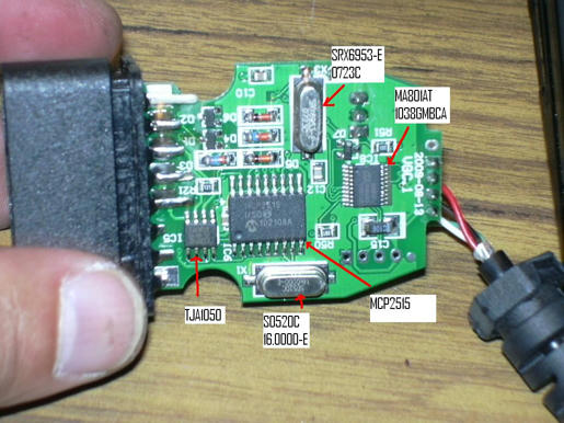
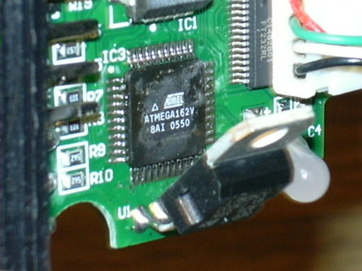
Yesterday I check out my Vag10.6 clone interface and took some pics: Originally Posted by eliotroyano
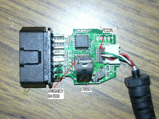
I check out the 7805 regulator is getting really "HOT" and it is only showing 3V at it 5V output. Also that test was on bench too, connecting Power and Ground only. Led starts flashing red and after that it turns off. Something should be in short. Anyone have a electrical or schematic diagram of this interface. Some help could be useful.
-
3rd May, 2012, 06:04 AM #2855DK Veteran

- Join Date
- May 2010
- Posts
- 634
- Thanks
- 140
- Thanks
- 195
- Thanked in
- 123 Posts
1. STC, D7, R50, R51=desolder.
2. GAL16V8 or ATF16V8 = desolder, reprogramm and resolder.
3 Solder 3 wire like in Aminebot's tutorial.
4. Reflash Atmega and/or FT232RL..
5. make a test using a proper VCDS and loader and with interface plugged into usb and obd2-car.
-
3rd May, 2012, 06:11 AM #2856DK Veteran
- Join Date
- Oct 2008
- Location
- On Earth
- Posts
- 1,865
- Thanks
- 37
- Thanks
- 181
- Thanked in
- 114 Posts
If you plugg it the 7805 has to have +12V (on OBD II side )-GND-+5V (LED side ) Originally Posted by eliotroyano
- pin 1 (V in ) +12V
- pin 2 GND
- pin 3 ( V out ) +5.0V
If it hasn't and become hot, change it
Good luck
-
3rd May, 2012, 02:32 PM #2857DK Veteran
- Join Date
- Aug 2009
- Posts
- 311
- Thanks
- 13
- Thanks
- 17
- Thanked in
- 12 Posts
Let me check it and I will let you informed. Originally Posted by mattydr67
Thanks a lot,
-
4th May, 2012, 03:28 AM #2858DK Veteran
- Join Date
- Aug 2009
- Posts
- 311
- Thanks
- 13
- Thanks
- 17
- Thanked in
- 12 Posts
 Change the 7805 regulator with a new one and I got the same result. When interface is cold led flash red almost 10 times, 7805 output is 5v and starts to drop to almost 3v and led flash red 10 times more when it turns off and 7805 is really hot and untouchable. If I let cold down half a minute it only flash red 8 or 10 times before led turns off. If reconnect power to interface just after test it, led flash red no more than 3 times before it turns off. In any case 7805 get really hot and voltage drop slowly until red more or less 3v. Originally Posted by eliotroyano

-
4th May, 2012, 05:01 AM #2859DK Veteran
- Join Date
- Oct 2008
- Location
- On Earth
- Posts
- 1,865
- Thanks
- 37
- Thanks
- 181
- Thanked in
- 114 Posts
I suppose that there it is short.
Check pins and PCB wires
Good luck
-
4th May, 2012, 05:28 AM #2860DK Veteran
- Join Date
- Aug 2009
- Posts
- 311
- Thanks
- 13
- Thanks
- 17
- Thanked in
- 12 Posts
Thanks for your support. But the weird thing is that I have used the cable in the past (last time was 2 months ago) and it work excellent. Now I try to use it and I got this issue. It can be kind of transistor damage or maybe atmega program issue????? Originally Posted by mattydr67
-
4th May, 2012, 08:27 AM #2861DK Veteran
- Join Date
- Mar 2010
- Location
- PT
- Posts
- 408
- Thanks
- 11
- Thanks
- 23
- Thanked in
- 15 Posts
Hey mate! Originally Posted by eliotroyano
You probably have a short, fried component or low impedance between tracks or pads.
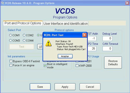
Post a print screen of the TEST result
Good luck.
Did it help? Push Thanks below
-
4th May, 2012, 01:03 PM #2862DK Veteran
- Join Date
- Aug 2009
- Posts
- 311
- Thanks
- 13
- Thanks
- 17
- Thanked in
- 12 Posts
Originally Posted by eliotroyano
Here are the pics KenshinPT. Originally Posted by KenshinPT
Thanks,
-
4th May, 2012, 03:12 PM #2863DK Veteran
- Join Date
- Mar 2010
- Location
- PT
- Posts
- 408
- Thanks
- 11
- Thanks
- 23
- Thanked in
- 15 Posts
If the interface was found, the UART-USB connection is OK. So FTDI is OK. Originally Posted by eliotroyano
Software or dump issues shouldn't cause hardware problems, like the one you have.
To conclude, in my opinion, you have a defective component, short circuit or low impedance between pads or tracks...
!!Check the whole PCB!!
Did it help? Push Thanks below
-
4th May, 2012, 03:33 PM #2864DK Veteran
- Join Date
- Aug 2009
- Posts
- 311
- Thanks
- 13
- Thanks
- 17
- Thanked in
- 12 Posts
Thanks a lot for you help KenshinPT, but do you have some schematic of this interface to following it?. SMD transistors could connect directly to OBD2 & CAN lines then, my thought is that something else connected to +5V line is in short or low impedance. Could be ATMega162V, but at least it starts few seconds when Vcc is enough and after that it turns off due to low voltage. Originally Posted by KenshinPT
-
4th May, 2012, 07:18 PM #2865DK Veteran
- Join Date
- Mar 2010
- Location
- PT
- Posts
- 408
- Thanks
- 11
- Thanks
- 23
- Thanked in
- 15 Posts
Your interface is RL, but I am 100% sure that this will help you Originally Posted by eliotroyano
If this helped you, please push the "thanks" below

Did it help? Push Thanks below
-


Bookmarks