
Thanks a lot for the help KenshinPT. I also founded here: http://www.digital-kaos.co.uk/forums...50/#post488533.Originally Posted by KenshinPT

Ok then according to the transistor output schematic the four (4) transistors in the back of the interface are for K & L lines replacing SI9241EY chips in the pdf diagram. And the other two (2) transistor near the ATMega162V could replace SI9200EY can driver in the pdf diagram. I will like to confirm this too.
In this case typically one of this SMD transistors could be in short when the ATMega162V or GAL16V8 look for it.
I am also starting to read whole thread looking for more info.

Results 2,866 to 2,880 of 12803
Thread: VAG-COM/VCDS EVERYTHING
-
4th May, 2012, 07:28 PM #2866DK Veteran


- Join Date
- Aug 2009
- Posts
- 311
- Thanks

- 13
- Thanks

- 17
- Thanked in
- 12 Posts

-
4th May, 2012, 08:55 PM #2867DK Veteran


- Join Date
- Apr 2009
- Location
- East Anglia
- Posts
- 5,942
- Thanks
- 1,513
- Thanks
- 1,400
- Thanked in
- 1,008 Posts
I have 10.6.4 is it easy to update to v11+ or no advantage
Many thanksOh and by the way if my post has been at all helpfull
please press the little THANKS tab
-
4th May, 2012, 09:59 PM #2868DK Veteran

- Join Date
- Mar 2010
- Location
- PT
- Posts
- 408
- Thanks
- 11
- Thanks
- 23
- Thanked in
- 15 Posts
In your hardware, you have 4 transistor for KKL but those 2 transistor you're saying that your cable has, are in fact diodes Originally Posted by eliotroyano

Your hardware, have both chips for CAN (CAN controller and CAN Transceiver)
And you're right, those 4 transistores could be in short.
Good luck
Regards.
Did it help? Push Thanks below
-
5th May, 2012, 01:12 AM #2869DK Veteran
- Join Date
- Mar 2010
- Location
- PT
- Posts
- 408
- Thanks
- 11
- Thanks
- 23
- Thanked in
- 15 Posts
Yes, the upgrade is easy. Originally Posted by teerak2uk
You need a programmer and the dumps.
Regards
Did it help? Push Thanks below
-
5th May, 2012, 01:08 PM #2870DK Veteran

- Join Date
- Oct 2009
- Posts
- 1,155
- Thanks
- 303
- Thanks
- 312
- Thanked in
- 194 Posts
Where are all this files located and where from we take ''codes.dat'' file to replace. Many thanks. Originally Posted by magadan
-
5th May, 2012, 01:31 PM #2871DK Veteran
- Join Date
- Oct 2008
- Location
- On Earth
- Posts
- 1,865
- Thanks
- 37
- Thanks
- 181
- Thanked in
- 114 Posts
Well you have to make a back up after you install first time or if your tools it is erased, uninstall the softwear , erased all registry and the reboot. After this you can isntall it back Originally Posted by autocargo
Good luck
For the peaple who do not using this every day, mu advise it is to install the softwear ( no internet connection ) then after you did a dignostic it is better to uninstall the softwear till you'll need to make another diagnostic in your car. When you need to make another dignostic you have to install the softwear back, do what you have to do and in the end uninstall the VCDS softwear till next time
Good luck
-
5th May, 2012, 02:54 PM #2872DK Veteran
- Join Date
- Oct 2009
- Posts
- 1,155
- Thanks
- 303
- Thanks
- 312
- Thanked in
- 194 Posts
Thank you mattydr67. I found those files. I would still like to know more about those files madagan talks about... Does it worth deleting and replacing this codes.dat file ?
Last edited by autocargo; 5th May, 2012 at 08:24 PM.
-
5th May, 2012, 03:15 PM #2873DK Veteran
- Join Date
- Oct 2008
- Location
- On Earth
- Posts
- 1,865
- Thanks
- 37
- Thanks
- 181
- Thanked in
- 114 Posts
I just erased d1,d2,d3 after every diagnostic session before using internet in that computer. Atmega never erased. Originally Posted by autocargo
Good luck
-
5th May, 2012, 04:18 PM #2874Top Poster
- Join Date
- Apr 2010
- Location
- RF
- Posts
- 133
- Thanks
- 1
- Thanks
- 39
- Thanked in
- 21 Posts
If the cable worked with this program well earlier. Now ceased to work. You already reprogrammed atmega. But the program continues to kill a cable. Then it is necessary to delete files "d1.bin, d2.bin, d3.bin" and to replace the file "codes.dat". They lie in folders near the set program. Originally Posted by autocargo
Or to make how mattydr67 advises. It is a post number 2874.
And you already tried to do so in version 11.11.3? Originally Posted by mattydr67
The program all the same tries to communicate with any non-constant IP.Last edited by magadan; 5th May, 2012 at 04:28 PM.
-
5th May, 2012, 05:08 PM #2875DK Veteran
- Join Date
- Oct 2008
- Location
- On Earth
- Posts
- 1,865
- Thanks
- 37
- Thanks
- 181
- Thanked in
- 114 Posts
I didn't tried becasue I don't have this version yet. I allready have 11.11.2 version and I can use internet connection in the same time with a diagnostic session. Originally Posted by magadan
I do not use any kind of protection ( nothing write in hosts file, no d1,d2,d3 erased, no firwall used, nothing, just VCDS softwear installed and this is it.
Good luck
-
5th May, 2012, 05:19 PM #2876DK Veteran
- Join Date
- Aug 2009
- Posts
- 311
- Thanks
- 13
- Thanks
- 17
- Thanked in
- 12 Posts
 Well I pass almost all night checking and testing everything in the board. Originally Posted by KenshinPT
I check out the transistors and are ok!!!! Weird... but anyway.
I found that K & L lines arrives up to these diodes:
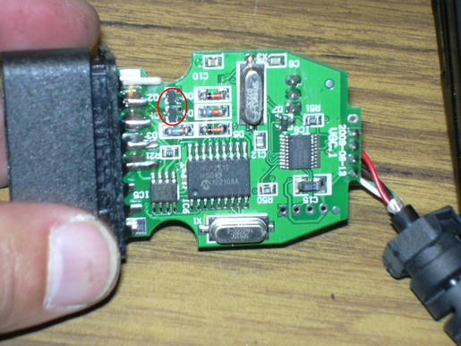
And continues to big signal diodes near these ones. After goes to the GAL16V8, I suppose this is the face erased IC. That contrast to the transistor diagram that you share me.
I check out the whole pcb and re-pass every solder of the main components in the front face, GAL, ATMega and resistors and capacitors near it.
With 7805 out resistance from +5V to GND is 2.5Kohms!!!!!!!!!.
Now interface starts, LED blinks red all the time, 5v is stable, 7805 get hot but not as before and I notice that ATMEga and GAL get hot not as 7805 but more than should be. In fact I got almost 80?C of the 7805, almost 60?C from ATMega and 50?C from GAL. Transistors, diodes and ICs in the back are cold.
Software still recognize interface but I got the following message:
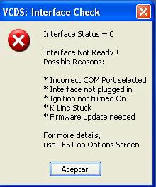
Also USBView recognize interface and MProg recognize FT232RL.
Now I really confused!!!!
-
5th May, 2012, 08:43 PM #2877Member
- Join Date
- May 2010
- Posts
- 68
- Thanks
- 8
- Thanks
- 1
- Thanked in
- 1 Post
I use a modded 11.2 with an interface with no GAL (help gained from here).
Should I be deleting D1,D2 & D3 each time?
Can any damage be done to my interface now that the STC and GAL are removed?
Also I am assuming for me to go any higher I would need a modded 11.xx and a higher than 1.84 dump?
(cable is just fine for me, just wondering)
Thanks in advance (cable is just fine for me)
-
7th May, 2012, 03:28 AM #2878DK Veteran
- Join Date
- Aug 2009
- Posts
- 311
- Thanks
- 13
- Thanks
- 17
- Thanked in
- 12 Posts
Friends do you have any idea what could be wrong????? Originally Posted by eliotroyano
-
7th May, 2012, 09:32 AM #2879Top Poster
- Join Date
- Apr 2010
- Location
- RF
- Posts
- 133
- Thanks
- 1
- Thanks
- 39
- Thanked in
- 21 Posts
In the first, cease to load identical photos, or reduce their size. Originally Posted by eliotroyano
In the second, compare the diagram of your cable with datasheet a cable.
Of the third be convinced that you didn't make errors when "tuning" cable.
In the fourth, give a cable for repair to experts. It is very difficult to repair a cable if it is impossible to take it in hands.
Try to replace the GAL chip with jumpers. Replace ?tmega. Check soldered details.
I don't see in your photos, three jumpers which are necessary that the cable earned.Last edited by magadan; 7th May, 2012 at 09:42 AM.
-
7th May, 2012, 11:16 AM #2880DK Veteran
- Join Date
- Mar 2010
- Location
- PT
- Posts
- 408
- Thanks
- 11
- Thanks
- 23
- Thanked in
- 15 Posts
I know this could be expensive, and this post won't help you with your problem... but if you want to keep things easy with VCDS, buy a cable with BL chip. Originally Posted by eliotroyano
Why? Because you don't need a loader and BL dumps works on any BL cables...
Regarding your problem, I am also without ideas... So do what Magadan wrote
Good luck
Did it help? Push Thanks below


Bookmarks